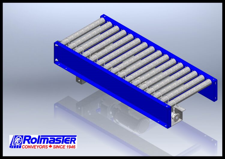
LINE SHAFT CONVEYOR DESCRIPTION:
LS – 1916HS Line Shaft Conveyor
CONVEYOR USAGE SUMMARY:
A medium duty conveyor ideal for applications that require a powered means for conveying products. Typically used in box handling applications. The friction drive design allows for product accumulation. Additionally, various accessories are available to control product flow.
LINE SHAFT CONVEYOR SPECIFICATIONS:
OVERALL LENGTH: 24” to 120”
OVERALL WIDTH: 15” to 51”
OVERALL HEIGHT: 14-23/75”
BETWEEN FRAME RAILS: 12” to 48”
DRIVE SHAFT: 1” Dia. Carbon Steel
MOTOR OPTIONS:
ELECTRICAL INPUT:
- 575V / 3 Phases / 60HZ
- 230 to 460 V / 3 Phases / 60HZ
- 110 V / 1 Phase / 60HZ
HP: ½, ¾ or 1
ROLLER CENTERS: 3”, 4-½”, 6”
ROLLER: 1.9” Dia. X 16 GA Galvanized Steel
ROLLER AXLE: 7/16” Hex Axle
SIDE CHANNELS: 7-½” X 1-½” X 11 GA
FRAME MATERIAL: Plain Steel
FRAME COUPLING: Butt Couplings
FRAME FINISH: 5017 Traffic Blue
OPTIONAL FINISH: 1021 Safety Yellow – 3001 Signal Red – 7015 Slate Grey – 9005 Jet Black – 9006 Aluminum White
CAPACITY: Varies pending roller centers and BFR. Contact us to review your application.
MODEL STRING: Conveyor Type – Mechanism Type – Roller Model – BFR – Rollers Centers Distance – Overall Length – Frame Type – Finish – End Connections & End Cover Type – RPM/Motor Number
Example: LS-D-1916HS-18-3-48-F8-5017-CA-100M17 (Line Shaft Conveyor, Driven, 1916 High Speed Roller, 18” Between Frame Rails Length, 3” Center to Center, 48” Overall Length, Frame8, 5017 Traffic Blue, Sprocket on Front Side/Collar on Back Side & No End Cover, 100 RPM/Motor 17)
Optional Features:
- Knee Braces or Mid Support Holes
- Side Rails (Toe Out Left, Right or Both)
- End Stop (Front, Rear or Both)
![]() Note: Shaft Ends are Always Keyed to Support Coupling Additional Sections in the Future.
Note: Shaft Ends are Always Keyed to Support Coupling Additional Sections in the Future.
LS-1916HS Line Shaft Drawing Download
LS - 1916HS Line Shaft Conveyor

